rotanova, a self-balancing scooter
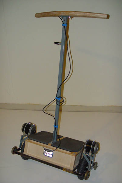
When the Segway first came out, I thought it was a great idea - until I found out what it sold for. I waited for the price to come down, but nothing happened. After reading about how it operates, it seemed a bit over-engineered, what with redundant batteries, motor windings, and balancing electronics. I began to wonder how simple a self-balancing scooter could be made and still have a reasonable margin of safety. I also found the design of the scooter to be a bit nerdy looking and wondered if a smaller, more skateboard-like product would have more appeal. So, in my spare time I began researching ways to determine balance as well as ways to simplify and shrink the overall size of the scooter, using off-the-shelf parts wherever possible. After quite a bit of effort and several prototypes, I gave up on trying to get a skateboard-style scooter going; it seemed that you really needed something to hang onto, and so my next thought was to put together a handlebar-type scooter. Once I had that working, I could try to figure out a way to shrink the self-balancing part into a smaller package.
How Self-Balancing Works
As you stand on the scooter and lean forward slightly, the scooter tips forward. With no power, you simply fall over and do a faceplant into the cold, hard ground. Under power, the scooter moves forward to move the center of gravity of you (and the scooter) just under the wheels. This is called the balance point. The trick here is to move just enough; too much and the center of gravity is then behind the scooter and so the motors must reverse to keep the scooter balanced. So, at a minimum, the scooter needs (a) to know if the platform is balanced, (b) control the motors to keep the scooter balanced, and (c) a power source to run the system. Oh, and since we might want to go in something other than a straight line, some sort of steering would be good to have too.
Balancing using an inclinometer
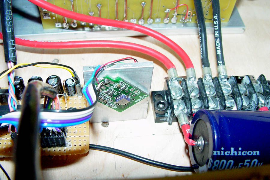
An inclinometer, or tilt sensor, measures the amount of tilt an object has with respect to gravity. For my scooter, I chose the MXR2999G from Memsic. This is a dual-axis accelerometer that uses heated gas as a proof mass. This means that a tiny amount of gas (nitrogen) is pulled by gravity, causing a temperature difference inside the accelerometer which then processes the difference and outputs a small voltage proportional to the tilt of the package with respect to gravity. The cost is minimal, about US$10 for a single unit. Note that the chip (shown at the center of the picture) is mounted at 45 degrees instead of parallel to the base of the scooter; this puts both the X and Y axes of the accelerometer in their middle ranges when the base is level. This gives better accuracy close to the balance point as well as canceling any drift or error between the two axes.
Calculating tilt using accelerometers
So now that we have a scooter deck with this dual-axis gadget, how do we find out what the tilt is? The amount of tilt is given by
tilt = y_accelerometer/x_accelerometer
When the base is in balance, the y value is the same as the x value, giving a tilt of y/x = 1/1 = 1. The arctangent of 1 is 45 degrees, so we subtract 45 degrees from the result to get the tilt:
tilt = arctan(y_accelerometer/x_accelerometer)-45.0
Using tilt to balance the scooter
Now that we know the balance, we have to control the motors so that tilting forward causes the motors to move the scooter forward. This is done with a PID (Proportional-Integral-Derivative) controller. A PID controller tries to do what the rider would do if the rider knew how much tilt the scooter had and had a throttle for controlling the motors. The proportional part of the controller is the amount of tilt; if the tilt is zero, the scooter is in balance and the motors do not have to move the scooter. The integral part of the controller accumulates tiny errors (deviations from balance) over time and as the errors grow, cause the motors to move in the direction necessary to restore balance. The derivative part of the controller watches the rate of change of the error over time and from that reduce the motor control so that quick changes do not overwhelm the controller. All three of these outputs are added together and fed to the motor controller.
Controlling the motors

The motors are 400W electric scooter motors with a chain drive. Each motor has its own control board. Each board uses four burly MOSFETs (IRFP2907, 75V 200A) connected in an H-bridge configuration and controlled by a PIC 16F88 microcontroller. The controllers receive a simple set of commands over a 38400 baud serial link from a main controller (a PIC 18F2620 running at 40MHz) that digitizes the accelerometer signals and runs the PID controller loop.
Power Supply and Miscellaneous
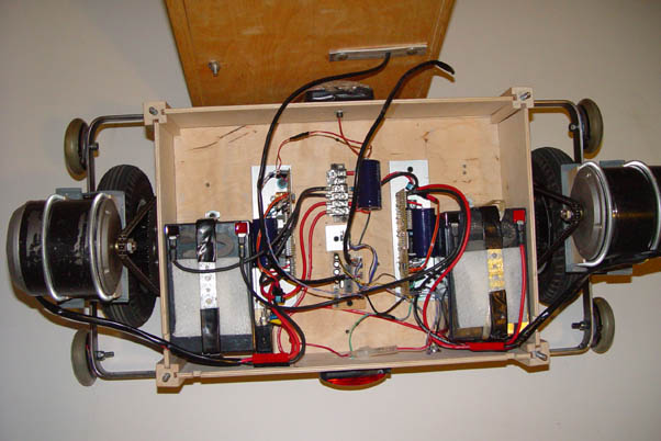
I used two 12V 10AH SLA (Sealed Lead Acid) scooter batteries connected in series for the power supply. From left to right the picture shows the left motor, the left SLA battery, the left motor controller. In the middle from top to bottom is the power distribution strip, the inclinometer, and the PID controller. On the right is the right motor controller, the right SLA battery, and the right motor. Metal pipe strapping covered in duct tape is used to keep the motors from shifting. I modified two LED bike lamps, one red and one white, and mounted them on the back and front of the scooter for visibility and also to tell me that the power is on. The back panel also contains a 50A circuit breaker and a connector for a 24V SLA battery charger. For steering, I added a center-off momentary switch (a joyswitch) to the handlebar and a left and right foot switch to the base to detect the presence of a rider. I added the four outrigger wheels (inline skate wheels) to the corners of the scooter for both safety and damage control; they allow the scooter to move during debugging without catching the bottom on the ground and causing damage or an inadvertent faceplant.
Debugging the scooter
I
got all the various subsystems running properly but the system as a
whole would not balance; after a great deal of effort I found that I
could not remove the acceleration effects of the motors from the tilt,
although I got close - my son could actually balance on the scooter but
nobody else could! After a great deal of experimenting and research, I
gave up on the idea of using only accelerometers to determine tilt and
started to look into using a rate gyro. The problem with using a rate
gyro is that it drifts, so it needs to be combined with the
accelerometer tilt to get a valid reading. You are supposed to combine
these sorts of signals using a Kalman
Filter,
but this requires quite a bit of number crunching and all I had to work
with was a PIC 18F2620 running at 40MHz. After some research (the
Internet is a wonderful thing), I found an article
on combining a rate gyro with a directional compass in a robot and
adapted it to use the accelerometer tilt to correct the rate
gyro
tilt. With
this code, any error accumulated by the gyro is corrected by using the
accelerometer tilt. The accelerometer tilt still has problems, but over
a long period it is more accurate than the rate gyro, which is more
accurate for short periods. The code is called every two milliseconds
and the motor PID loop is called every twenty milliseconds. This 1:10
ratio keeps the scooter well balanced. Once I had the rate gyro
code working, tuning the PID loop and getting the scooter balanced went
very quickly. Now even I could ride the scooter without falling off!
Tuning
the PID consisted of setting the gains for the I and D parts of the
loop to zero, then increasing the P(roportional) gain till the scooter
started to oscillate with no rider on board. I then backed the P gain
off a little and increased the I gain till the scooter started acting
oddly - riding it felt like you had some sort of slippery
spring
underfoot. Turning on the scooter with no rider, I could see the
handlebar sweep back and forth several times till the oscillation died
out. I then backed off on the I gain a little and increased the D gain
until the handlebar oscillated wildly only once and then damped down
rapidly. My son Matt helped with the testing as I was busy tweaking the
scooter from my laptop.
Adding the Gyro
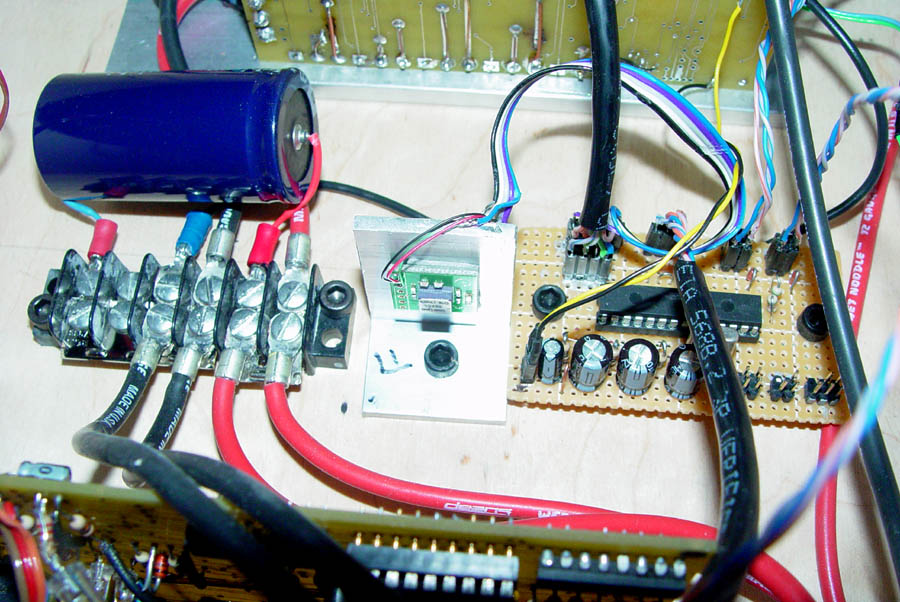
The picture shows the ADXRS300 rate gyro mounted on a breakout board from Spark Fun electronics. The board is mounted to an aluminum bracket with double-sided foam tape. The accelerometer board is mounted on the opposite side of the bracket. The boards at the upper and lower parts of the picture are the left and right motor controller boards, and the board to the right of the gyro bracket is the PIC 18F2620 PID loop controller board. The power distribution strip is to the left of the gyro bracket.
Observations and Acknowledgements
Now that I've actually built the scooter and got it running, I can see why some of the Segway features are not so much over-engineering than a way to handle some of the boundary cases that come up when developing a product that interacts with the real world.
A case in point: Suppose the scooter is moving forward and the left wheel hits an obstruction. The left wheel then stops (or slows down rapidly) and the scooter pivots counterclockwise around the left wheel. If the scooter is moving rapidly, this may cause the rider to be thrown off the scooter or otherwise lose control. So, I can see the value of sensing the speed of each wheel and using that to increase the speed of the left wheel so that it can overcome the obstruction. This would also help with steering.
I still don't see the value of having redundant motor windings or electronics; these normally have an adequate MTBF (mean time between failures), so why add the expense of redundancy? Perhaps it is due to its being a new product, although as a cost-reduction measure some of the redundant features should be removed after examining the real-world performance data.
Now that the scooter is done, I revisited the skateboard concept, which is shown on the skatanova project page. Sony recently patented this idea, so it will be interesting to find out what kind of product they turn out. I can only hope it is less spendy than Segway's products.
Much thanks goes to my son, Matt, who was a good helper and tester, as well as vendors CCS Computer (the PICC Compiler), Spark Fun electronics, Mouser Electronics, Digi-Key, and PCB123.
If you've got questions regarding this project, email me at: p r o j e c t _ q u e s t i o n s at k y s o t e c h . c o m
tony ozrelic, feb. 2007